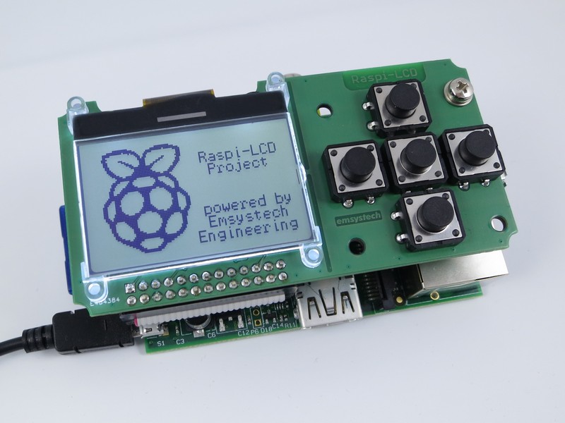
A number of years ago I bought a neat little LCD/Button add-on module for my 1st Gen Raspberry Pi. The company that produced these (Emsystech Engineering, Germany) no longer produce them and they no longer host information about them on their website. This is a mirror of the info that I've managed to collate from a number of sources, primarily the Wayback Machine.
The following is text that has been copied from Emsystech's website after being auto-translated by Google, as the original was in German which I don't understand. It has been lightly edited to remove information that is either no longer relevant or refers to websites/products that can no longer be found and to include additional information that was not originally provided (or available to) Emsystech. This includes projects that have implemented support for the module in other programming languages. I have also corrected some of Google Translate idiosyncrasies. I've kept it here for my own reference, and to assist anyone else who may have purchased these modules and is struggling to find information on them. I can't offer any support on the product itself, other than by providing the information present here.
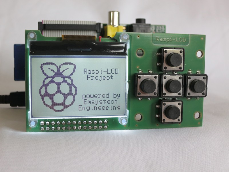
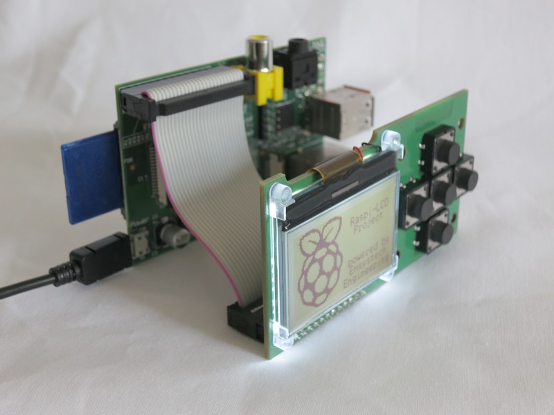

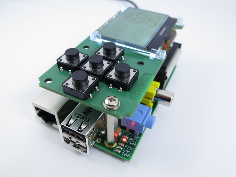
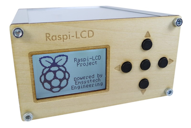
With this module, a Raspberry Pi can be extended by a display and buttons. For many applications, a typical PC monitor and keyboard is too large and unwieldy. This gap closes the Raspi LCD. Projects such as web radios, streaming clients, home automation systems, ... can use this hardware. The circuit and a source code in C are available as open source. The basic "driver functionality" and necessary hardware access functions are implemented in this sample application. The keyboard area can be equipped with various buttons or separated. On the back of pads for receiving pin headers are already provided.
- 1.8 inch display
- Software adjustable contrast
- White LED backlight (software controllable)
- 5 buttons (6 × 6 or 12x12mm)
- Connection possibility for UART and I2C
Reference Documents
Language Bindings
Projects
Misc
- https://github.com/pboehm/libraspilcd
Display
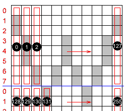
The display used or its graphic controller is connected via SPI interface. In the current version this is emulated in the software (-> no driver necessary). The display with its 128 x 64 pixels is in principle a 1kByte large memory, with which each bit corresponds to a pixel. In the software, the coordinates (x / y) correspond to the top left corner (0/0) and bottom right (127/63). Since the smallest organizational unit is one byte, 8 pixels are always transmitted and stored together. The least significant bit of the first byte is the origin in the upper left corner. Then follow for all 1024 bytes, the bits: D1 = (0/1), ... D7 = (0/7), etc. Since the memory of the display only describe, but not read, there is a small problem with the pixel-wise Presentation. Should a function change a single pixel, The other 7 bits of the associated byte must also be transferred. For this reason, a so-called frame buffer is implemented in the software. This is a 1: 1 memory image of the display. All operations are done with the framebuffer. With the function LCD_WriteFramebuffer(); then the output and display is done on the display.
Output of the text "Hello World":
LCD_SetFont(0);
LCD_PrintXY(0,0, "Hello World");
Drawing a rectangle with transparent fill and two pixel line width:
LCD_SetFillColor(-1);
LCD_DrawRect(10,10,100,40,1);
Bitmaps can be converted to C arrays using the BMP2C V1.0 program . eg: const uint8 bmp_raspi [458] = {57, 64, 0×00, ... 0×00};
Output of bitmap at position(0/0):
LCD_DrawBitmap(0,0, bmp_raspi);
Buttons
The individual keys switch to ground when the key is pressed. Since the corresponding GPIO PINs are configured as an input with pullup, a depressed key means logical 0, an unpressed key logical 1.
The function UpdateButtons(); ensures that the state of the buttons is stored in the two variables ButtonPressed and Button as one bit each. Macros such as: BUTTON_PRESSED_UP, BUTTON_PRESSED_RIGHT, ... allow comfortable use of the keyboard.
Backlight
On the Raspi LCD there is a switching transistor for controlling the LED background illumination. The corresponding GPIO pin can be set via the function SetBacklight(); be controlled.